Red Baron

SEARCH RESAULT : 글 검색 결과 - Network (총 5개)

POST : Network

AF_xxx versus PR_xxx

To quote from W. Richard Stevens 'Unix Network Programming V1 2ed p.88':
(forgive any typos)

AF_xxx versus PR_xxx

The AF_ prefix stands for "address family" and the PF_prefix stands for
"protocol family". Historicly, the intent was that a single protocol family
might support multiple address families and that the PF_ value was used to
create the socket and the AF_ value was used in socket address structures.
But in actuality, a protocol family supporting multiple address families has
never been supported and the <sys/socket.h> header defines the PF_ value
for a given protocol to be equal to the AF_ value for that protocol. While
there is no guarentee that this equality between the two will always be true,
should anyone change this for existing protocols, lots of existing code would
break. To conform to existing coding practice, we use only the AF_ constants
in this text, although you may encounter the PF_ value, mainly in calls to
_socket_.


top

posted at

2007. 1. 31. 01:38


POST : Network

voip E-model 에 대한 간략한 메모

* 이 문서에 대한 권한은 저자에게 있습니다.

퍼 가실때는 출처를 표시하여 주시고 메일로 연락을 주십시오. dif001@hamail.net

e-model 에 근거한 R 값을 산출하기 위해서는 기분적으로 ip layer에서 볼 때 총 3가지의 근거 요소를 기반으로 값을 산출한다.

1.       delay

2.       packet loss

3.       jitter(delay variation)

그외 echo

그리고 주의 해야할점

사용자의 음성 측정중 패킷의 망가짐(voice distortion)

등을 측정 할수 있는 방법으로서는 BER(bit error rate) FER (frame error rate) 이 두가지는 실제적 음성 데이터 즉 RTP상에 실려오는 실제 음성 데이터의 에러 검출 방식에 따라서 산출해 낼 수 있다.

PSQM(perceptual speech quality measurement)(ITU-T P.861) ß MOS와 직접적인 연관관계는 없다.

ITU-T G.107 결과값 R을 가지고 MOS산출을 할수 있는 공식.

FOR R<0             : MOS=1

FOR 0<R<100     : MOS=1+0.035R+7R(R-60)(100-R)*10^-6

FOR R>100          : MOS = 4.5

ITU-T G.107 Factor R 공식

R=R0+Is+Id-Ie+A

R0  회선 잡음, /수화 실내 경음, 가입자 선 잡음에 의한 주관적 품질 저하

Is OLR(라우드네스), 측음(sidetone) , 양자화 변형에 의한 주관적 품질저하

Id 송신한 사람의 에코, 수신한 사람의 에코, 절대 지연에 의한 품질저하

Ie 낮은 비트레이트(BER) 부호화, 패킷/셀 손실 등에 의한 주관적 품질저하

A  모바일 통신 등의 편리성이 주관적 품질(만족도) 에 끼치는 영향을 보완(현재 프로젝트에서는 0으로 판단하면 됨)

top

posted at

2006. 12. 9. 14:32


POST : Network

Codec별 Frame Size 와 특성표

http://blog.naver.com/dif001/20007086008

Codec

G.711

G.723.1

G.726-32

G.729

Coding rate (kb/s)

64

5.3-6.3

32

8

Frame size (ms)

0.125

30

0.250

10

Algorithm

PCM

MP-MLQ

ADPCM

CS-ACELP

Processing delay (ms)

0.125

30

0.250

10

Look ahead delay (ms)

0

7.5

0

5

Payload (Bytes)

1

20-24

1

10

Quality

Good

Good/fair

Good

Good

Complexity

Lowest

Highest

Low

High

Table 1. Selected ITU voice coders and key characteristics.


참고 사이트

http://www.comsoc.org/livepubs/surveys/public/2004/apr/scheets.html

Voice Coder

     POTS networks almost universally use the ITU G.711 64 kb/s PCM standard. As previously noted, this type of coder outputs 8 bits every 1/8000th of a second, that is, the frame of this coder is 1/8000th of a second, and the frame size is 8 bits.
     Other coders exist that can reduce the generated bit rate, but usually with a slightly reduced perceived quality.
Table 1 compares selected ITU coders, including their associated bit rates [2, 3].
     Of these codes, G.729 has evoked considerable interest for VoIP providers as it has comparable quality to G.711, but at a greatly reduced bit rate. G.729 has a frame length of 10 msec, and its compression algorithm outputs 80 bits every 1/100th of a second, yielding an 8 kb/s bit rate.
     POTS TDM backbones are based around fixed-rate coders. For example, a G.711 coder outputs 64 kb/s at all times, regardless of whether or not the voice source is talking or listening. The statistical as-needed allocation of backbone bandwidth on VoIP networks offers the opportunity to deploy variable-rate coders, which output traffic at one bit rate when the voice source is talking, and a lower bit rate (possibly zero) when the voice source is quiet. For example, G.729B with silence suppression examines each 10 msec voice frame and makes a voice/no voice decision. If the coder detects voice energy, it will output the standard 80 bits of compressed, digitized voice for that frame. If the coder decides this frame does not contain voice energy, the coder will output a reduced block of bits containing comfort noise, information that the receiver will use to generate background noise so that the user does not think the connection has been lost [3]. Alternatively, the coder could output nothing at all and the receiver could generate comfort noise.
     Experiments have shown that in a typical two-way interactive voice conversation, voice sources are only active 40 percent of the time [4]. The 60 percent idle time includes pauses while listening to the other party talking, as well as pauses between sentences, and even pauses between some words. A G.729B coder with silence suppression will output 8 kb/s during talk spurts (40 percent of the time), and nothing or a reduced bit rate during intervening silence intervals (60 percent of the time). The use of silence suppression potentially allows a G.729 coder to reduce its average output from 8 kb/s to 3.2 kb/s (alternating 8 kb/s and 0 kb/s bursts).

top

posted at

2006. 12. 9. 14:32


POST : Network

voip - jitter 정의

* 이 문서에 대한 권한은 저자에게 있습니다.

퍼 가실때는 출처를 표시하여 주시고 메일로 연락을 주십시오. dif001@hamail.net

1.        Jitter

Jitter는 네트웍 구간에서 Packet전송 지연 편차( delay variation) 이다.

사용자 삽입 이미지

참고.2에 나타난 수치들을 기준으로 값을 낸다.


RTP3-RTP4 delay

Local delay(codec delay) : 46744(5843) - 46504(5813)  = 240 (codec delay:30ms)

240 30msec으로 환산할 수 있다.

Local delay codec처리를 하는 시간으로서 codec의 종류에 따라 다른 일정한 시간을 가진다. 기본적으로 160(20ms) 240(30ms) 두가지 값을 가지게 된다.

Capture delay : 20.508 20.478 = 0.030 (30ms)

Packet을 수집하고 packet간의 딜레이를 측정한 것이다.

이 값은 msec까지만 측정한 것으로 실측에서는 usec에서의 오차가 있는 것으로 나타났다.

이상의 값으로 측정하였을 때

Network delay

Tn'' = T1'-T1

이상의 식으로 값을 내었을 때 아래와 같다.

RTP3-RTP4 delay

30ms(capture delay) 30ms(local delay) = 0

RTP4-RTP5 delay

46984 46744 = 240 (30ms)

20.540 20.508 = 0.032 (32ms)

32ms 30ms = 2ms

RTP5-RTP6 delay

47224 46984 = 240 (30ms)

20.569 20.540 = 0.029 (29ms)

29ms 30ms = -1

Jitter   = (RTP4-RTP5) - (RTP3-RTP4)

           = |2 0| = 2

           = (RTP5-RTP6) - (RTP4-RTP5)

           = |2 + 1| = 3

                  = (2+3)/2

                  = 2.5ms

이상의 네트워크상의 Packet 전송 지연 편차를 구하는 방법이다.


2.        End-To-End delay

End-To-End delay는 유저간의 전송시간을 측정하는 것이다.

사용자 삽입 이미지

그림에서 나타난 굵은색 부분이 총 one round trip 이다.

프로젝트에서 필요한 부분은 half round trip으로서 이값은 one round trip 값을 2로 나눈 값이다.

구하는 방법은 아래와 같다.

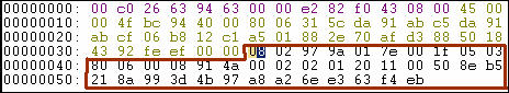
최초 RTCP 전송이 user1에서 user2로 전송될 때의 패킷 (Sender Report)

사용자 삽입 이미지

NTP reference timestamp

NTP second       : 00 05 05 77

NTP fraction        : f3 00 00 00

이 값은 user1측에서 데이터를 전송할 때의 시간이다.

이 값을 받은 user2는 일정시간(실측시간 5sec) 이 지난후에 RR(Receiver Report)메시지를 전송한다.

사용자 삽입 이미지

LSR (Last Send Report timestamp)            : 05 77 f3 00

DLSR (delay since last SR)                       : 00 03 93 00

LSR SR메시지 상의 NTP timestamp의 일정부분을 추출한 값이다.

사용자 삽입 이미지

이 값은 timeval(msec, usec)으로 이루어진 값으로써 이값에서

msec부분의 하위 2byte usec부분의 상위 2바이트를 추출하여 Round-trip값을 구하기 위한 지표값으로 사용한다.

DLSR SR메시지를 전달받고 RR메시지를 전송하기까지의 Local Processing Delay를 나타낸다 이 값은 timeval(msec, usec)형태로 이루어 져 있다.

위의 기본지식을 바탕으로 실측데이터를 가지고 End-To-End delay를 측정한다.

1.       user1-SR (NTP timestamp)
NTP second        : 00 05 05 77
NTP fraction        : f3 00 00 00

2.       agent-SR 수집 시간(Agent)
20.224(sec)

3.       user2-RR-LSR,DLSR
LSR        : 05 77 f3 00
DLSR      : 00 03 93 00

4.       Agent-RR수집시간
23.793(sec)

5.       End-To-End delay
23.793-20.224-3.376 (
반올림
) = 0.193 (one round trip)
0.193/2 = 0.096 == 96ms


top

posted at

2006. 12. 9. 14:26


POST : Network

H.225(Q.931)

아래 자료는 VoIP패킷 분석을 하시려는분들을 위해 일부 자료를

오픈 합니다.

별게 아닌걸수도 있지만...유용하게 사용하셨으면 합니다.

그리고 퍼가실 경우 출처를 밝혀주셨으면 합니다.

* 이 문서에 대한 권한은 저자에게 있습니다.

퍼 가실때는 출처를 표시하여 주시고 메일로 연락을 주십시오. dif001@hamail.net


1.1.      H.225(Q.931)

먼저 H.225 메시지의 구체적인 모습은 아래와 같다.

8

7

6

5

4

3

2

1

Octet

Protocol Discriminator

1

0

0

0

0

Length of call reference bits

2

Call reference value

3 (-4)

0

Message type

Information Elements

H.225 structure

그림 1-4 H.225 header

실제 패킷의 형태는 아래와 같다.

sniffer capture 화면 (아래 참조)

그림 1-5 H.225 alerting

sniffer capture 화면 (아래 참조)

그림 1-6 H.225 header

H.225 헤더의 각 필드의 뜻은 아래와 같다.

Protocol discriminator
Distinguishes messages for user-network call control from other messages.
사용자 – 네트워크 간의 콜 제어 메시지를 다른 메시지와 구분하기 위해 사용

0000 1000 (0x08) Q.931 사용자 – 네트워크 간의 콜 제어 메시지로 제안(권고)되어 있음.


Length of call ref
The length of the call reference value.

콜 참조 값의 길이

Call reference value

Identifies the call or facility registration/cancellation request at the local user-network interface to which the particular message applies. May be up to 2 octets in length.

Bit

8(locate)

0

콜 참조값을 생성한 곳에서 보내진 값

1

콜 참조값을 생성한곳으로 보내지는 값

최초의 값(8bit)를 제외한 값이 콜 참조 값이 된다.

) Call reference field 179A

0001 0111 1001 1010

  콜 참조 값 -> 6042 (dec)

콜 참조값을 생성한 곳에서 보내진 값

Message type
Identifies the function of the message sent. The following message types are used:

000

xxxxx
00001
00010
00111
01111
00011
00101
01101

01

02

07

0f

03

05

0D

Call establishment messages:
ALERTING
CALL PROCEEDING
CONNECT
CONNECT KNOWLEDGE
PROGRESS
SETUP
SETUP ACKNOWLEDGE

001

xxxxx
00110
01110
00010
00101
01101
00001
00000

Call information phase messages:
RESUME
RESUME ACKNOWLEDGE
RESUME REJECT
SUSPEND
SUSPEND ACKNOWLEDGE
SUSPEND REJECT
USER INFORMATION

010

xxxxx
00101
01101
11010
00110
01110

45

4D

5A

46

4E

Call clearing messages:
DISCONNECT
RELEASE
RELEASE COMPLETE
RESTART
RESTART ACKNOWLEDGE

011

xxxxx
00000
11001
11011
01110
11101
10101

7B

6E

7D

75

Miscellaneous messages:
SEGMENT
CONGESTION CONTROL
INFORMATION
NOTIFY
STATUS
STATUS ENQUIRY

Information elements
Two categories of information elements are defined: single octet information elements and variable length information elements, as shown in the following illustrations

8

7

6

5

4

3

2

1

Octet

1

IEI

Contents of IE

1

Single octet information element format (type 1)

8

7

6

5

4

3

2

1

Octet

1

IE Identifier

1

Single octet information element format (type 2)

8

7

6

5

4

3

2

1

Octet

1

IEI

1

Length of contents of IE

2

Contents of IE

3-n

Variable length information element format

이상의 부분은 H.225 header(Q.931) 이다.

위의 정보를 참고 하여 실제 프로토콜을 분석

08

02

97

9a

01

7e

00

1f

08 – Q.931메시지를 나타낸다.

02 – length of call ref

97 9a – call reference number (최상위 1bit를 제외한 나머지 bit가 실제 length)

01 – message type(alerting)

실제적으로 메시지를 전달하게 되는 데이터 부분은 Q.931부분은 이 헤더 뒷부분에 저장 되어 전달 되게 된다

Packet상에서 Q.931메시지의 시작은 7e 부분이다.

7e – User – network- user

0111 1110(35)User - User

이하의 부분은 IE(Information Element)의 구체적인 정의부분이 필요하다.

이 정보를 확보한 후 Byte단위의 IE들을 Bit단위로 분석한다.

사용자 삽입 이미지

그림 1-5 H.225 alerting
사용자 삽입 이미지

그림 1-6 H.225 header

top

posted at

2006. 12. 9. 14:21


CONTENTS

Red Baron
BLOG main image

RSS 2.0Tattertools
공지 아카이브
최근 글 최근 댓글 최근 트랙백
카테고리 태그 구름사이트 링크